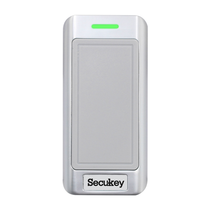


SK2-RX (1-Wire)
1-Wire Keypad Reader (EM+HID+MF)
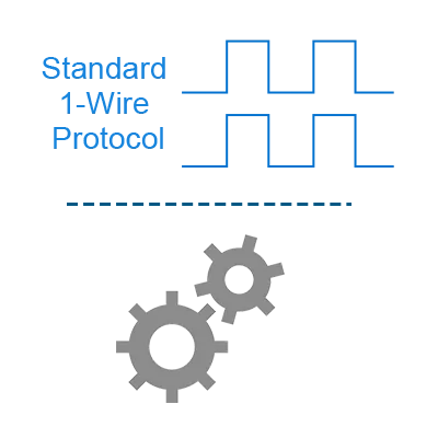
Standard 1-Wire protocol
Power Supply: 9-80V DC
Built-in antenna
Supports 125kHz EM & 125KHz HID & 13.56MHz Mifare cards
Low Power consumption
Built-in buzzer
Read range up to 8cm
Waterproof, conforms to IP67

Sales Inquiry
Description of 1-Wire 125 KHz & 13.56MHz Proximity Card Reader
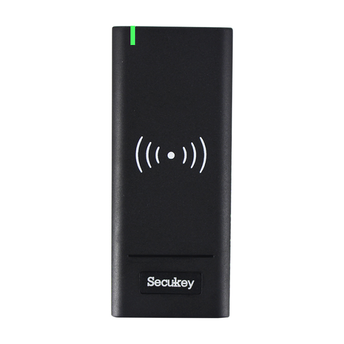
SK2-RX (1-Wire) is a standard 1-Wire Protocol keypad reader.
It can read 125KHz EM & HID cards and 13.56MHz Mifare Cards.
Because of waterproof, it can be mounted either indoor or outdoor in harsh environments.
It can read 125KHz EM & HID cards and 13.56MHz Mifare Cards.
Because of waterproof, it can be mounted either indoor or outdoor in harsh environments.
Features of 1-Wire 125 KHz & 13.56MHz Proximity Card Reader
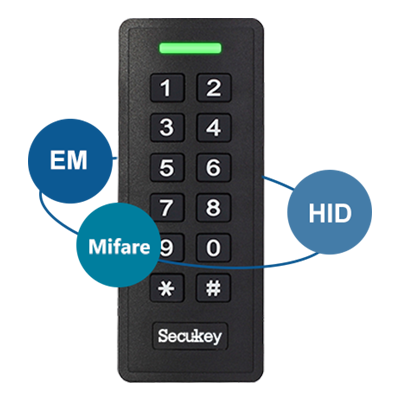
3 in 1 Universal Keypad
for EM, Mifare and HID card
Waterproof IP67
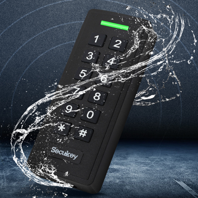
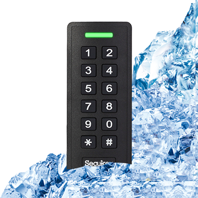
-40℃ Low working temperature
FAQs of1-Wire 125 KHz & 13.56MHz Proximity Card Reader
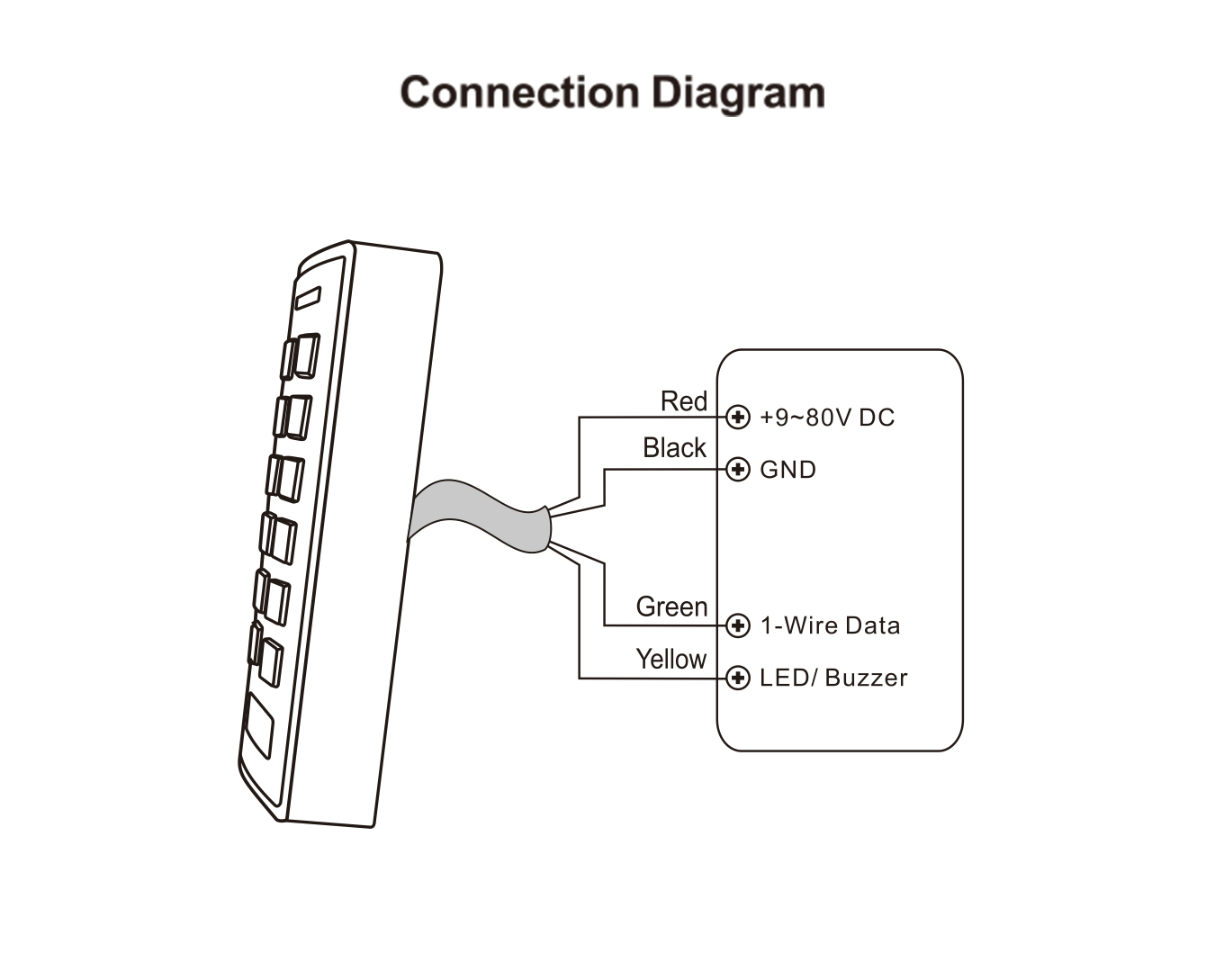
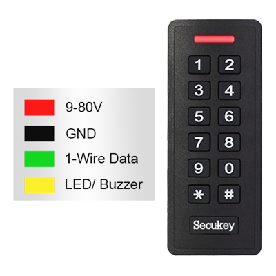
1. What are the pin functions and how do I wire this reader?
The reader has 9 pins with the following functions based on the label:
| Pin | Function |
|---|---|
| 1 | 1-Wire Data |
| 2 | LED / Buzzer Control |
| 3 | GND (Ground) |
| 4 | 9–18 VDC Power Input |
2. What is the 1-Wire protocol, and how is it different from Wiegand?
1-Wire is a communication protocol that uses a single data line (plus ground and power) to transmit data between the reader and the controller. Unlike Wiegand (which uses two data lines: D0 and D1), 1-Wire is simpler and requires fewer wires, making installation easier and reducing wiring costs. However, it requires a controller that supports the 1-Wire protocol. If your controller uses Wiegand, you will need a protocol converter or a reader that supports both protocols.
3. Can I control the LED and buzzer from my controller?
Yes, Pin 2 is designated for LED/Buzzer control. When connected to a controller output (typically an open-collector or relay output), the controller can:
- Send a signal to activate the LED (e.g., green flash for granted access)
- Trigger the buzzer for feedback (e.g., beep for card read)
If Pin 2 is not connected, the reader may still provide basic LED/buzzer feedback (e.g., red LED standby, beep on card read) using its internal logic. Check your specific model for default behavior.
4. What is the typical read range for this reader?
The read range depends on the card type and installation environment:
The read range depends on the card type and installation environment:
- 125 kHz cards: Typically 3–8 cm (approximately 1.2–3.1 inches)
- 13.56 MHz cards: Typically 2–5 cm (approximately 0.8–2.0 inches)
For optimal performance, install the reader on a non-metallic surface and avoid placing it near large metal objects, which can interfere with the RF field.